Full Wave Controlled Rectifier Circuit Diagram Full-wave Rec
Full wave bridge rectifier circuit diagram In-depth guide to full wave rectifier What is full wave rectifier ?
full wave rectification diagram - Wiring Diagram and Schematics
What is single phase full wave controlled rectifier? working, circuit Center tapped full wave rectifier circuit diagram Full-wave rectifier circuit with resistive load.
Full wave rectifier basics, circuit, working & applications
Single phase full wave rectifier circuit diagramFull wave rectification diagram Rectifier advantages disadvantages electronicscoachSolved build the full wave bridge rectifier circuit shown in figure.
Rectifier disadvantages advantages electronicscoachFull wave rectifier circuit working and theory With neat circuit diagram and waveforms explain the operation of fullHalf wave rectifier circuit diagram.

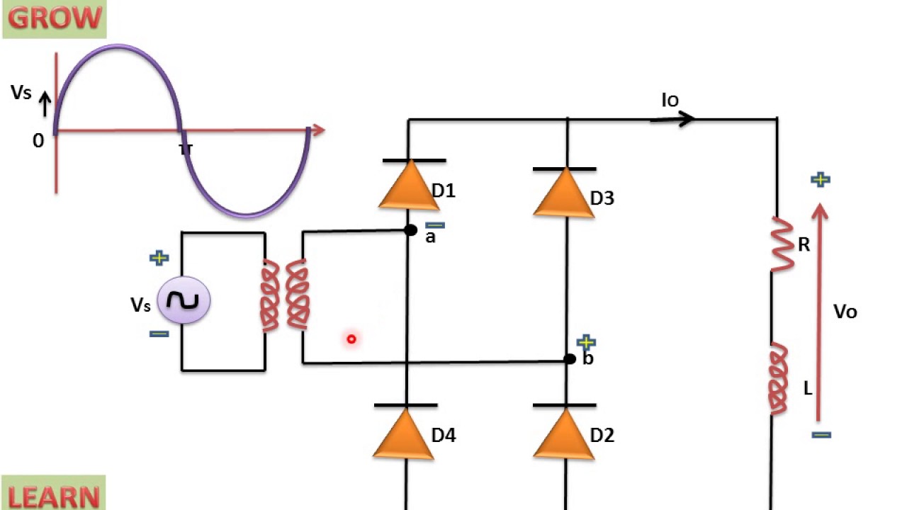
What is single phase full wave controlled rectifier? working, circuit
What is full wave rectifier circuit diagram working advantagesFull wave controlled rectifier circuit diagram Rectifier thyristors diodes constructedHalf wave & full wave rectifier: working principle, circuit diagram.
What is single phase half wave controlled rectifier (with r loadMake three phase full wave rectifier circuit. What is single phase full wave controlled rectifier? working, circuitWhat is full wave rectifier ?.

Full wave controlled rectifier circuit diagram
What is single phase full wave controlled rectifier? working, circuitIn-depth guide to full wave rectifier .
.
.jpg)


